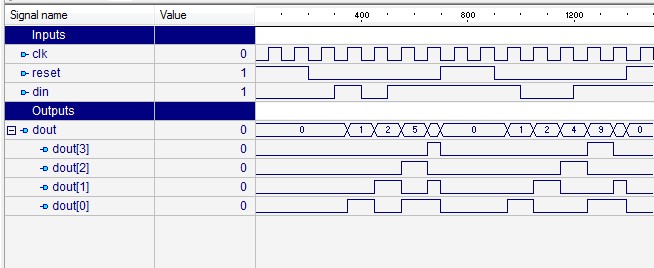
8 Bit Serial To Parallel Converter Verilog Code
Library IEEE; use IEEE.STD_LOGIC_1164. ALL; use IEEE.STD_LOGIC_ARITH.
ALL; use IEEE.STD_LOGIC_UNSIGNED. ALL; entity P2S is port ( Serial_out: out std_logic; clk: in std_logic; Parallel_data: in std_logic_vector( 15 downto 0); DataReady: in std_logic); end P2S; architecture Behavioral of P2S is signal OldReady: std_logic:= '0'; signal Shreg: std_logic_vector( 15 downto 0); begin process (clk) begin if (clk 'event and clk = '1') then Shreg.
Serial or parallel output. The shift register output mode may be. Free download lagu senam aerobik terbaru. Following is the Verilog code for an 8-bit shift-left register with a positive-edge clock.
Ya input is fixed length of 16 bit but this parallel to serial converter logic should be programmable when ever the data will arrive then dat should get serialized. For example 1st i got the data of 6 bit length at that time that data should be latched then it should get serialized. Similarly some other time when i get the data of length10 bit even in same way that should get serialized.
This means our logic should be 1 time programmed instead of runtime programmable. I think u got my point. > For example 1st i got the data of 6 bit length at > that time that data should be latched then it should get serialized. > Similarly some other time when i get the data of length10 bit even in > same way that should get serialized. Thats exactly, what my previously posted code does. > 1st i got the data of 6 bit length > some other time when i get the data of length10 bit even in same way And HOW can cou see this difference of 4 bits on a 16 bit vector? How can you KNOW the witdh of the actual vector?

> I think u got my point Yes, i do, but not vice versa. Draw a picture with different parallel input vectors and how the have to occur on the serial output. EDIT: > it is nt simulating Why?
Whats the problem? > counter Serial_out.

A serial-in, parallel-out shift register is similar to the in that it shifts data into internal storage elements and shifts data out at the serial-out, data-out, pin. It is different in that it makes all the internal stages available as outputs.
Therefore, a serial-in, parallel-out shift register converts data from serial format to parallel format. An Example of Using Serial-in, Parallel-out Shift Register If four data bits are shifted in by four clock pulses via a single wire at data-in, below, the data becomes available simultaneously on the four Outputs Q A to Q D after the fourth clock pulse. The practical application of the serial-in, parallel-out shift register is to convert data from serial format on a single wire to parallel format on multiple wires.
Let’sl illuminate four LEDs (light emitting diodes) with the four outputs ( Q A Q B Q C Q D). The above details of the serial-in, parallel-out shift register are fairly simple.
It looks like a serial-in, serial-out shift register with taps added to each stage output. Serial data shifts in at SI (Serial Input). After a number of clocks equal to the number of stages, the first data bit in appears at SO (Q D) in the above figure. In general, there is no SO pin. The last stage (Q D above) serves as SO and is cascaded to the next package if it exists. Serial-in, Parallel-out vs.